Robot Drive Systems
The term used for a mechanism that drives a Robot arm is actuator. These actuators may be
electric motors of some type or hydraulic or pneumatic cylinders. Hydraulic and pneumatic
actuators are generally suited to driving prismatic joints since they produce linear motion
directly. They are often referred to as linear actuators. Electric motors which produce
rotation are more suited to driving revolute joints. However various gear mechanisms may be
used to convert linear to rotary motion and vice versa.
Hydraulic Actuators - Pneumatic Actuators

Hydraulic Actuators
A common example of a hydraulic device is the braking system of a modern car, here only
moderate force applied to the brake pedal produces a large enough force at the brake pads to
stop the car. The underlying principle of all hydraulic systems is Pascal's Law, which states:-
If external pressure is applied to a confined fluid, the pressure is transferred without
loss to all surfaces in contact with the fluid.
Figure 1 shows how Pascal's law is put to use in a simple hydraulic drive mechanism.

Applying Pascal's law :-
A liquid is confined in a cylinder between the two pistons A and B. If a force of 3kg is
applied to B which has a surface area of 1 sq. cm. There will be a pressure in the liquid of
3 kg per sq. cm or 300 KPa. According to Pascal's law there is also a pressure on the surface
of piston A. Piston A has a surface area of 20 sq. cm the force on piston A would therefore
be 60 kg. It appears we have multiplied the input force 20 times. Now because the liquid is
incompressible, then if piston B is moved through 20 cm then piston A will only move
through 1 cm, therefore this can be summed up with the equation :-
Force x Distance moved at input = Force x Distance moved at output
Returning to the example of the car breaking system, it can now be easily explained. When
the break pedal is pressed it travels a few centimetres, but the pistons which operate the
brakes in the wheels move only one or two millimetres i.e. a small force applied to the brake
pedal is used to produce a much larger force at the brakes.
The Double Acting Cylinder

Here, movement of the piston in both directions can be controlled by pumping liquid into the
cylinder. Selecting port B as the inlet ( A closed and D open ) will move the piston outwards.
Selecting C as the inlet ( D closed and A open ) will move the piston inwards.
The hydraulic transfer valve
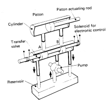
A practical arrangement of the double acting cylinder, allowing very precise control, is
shown below. The complete system consists of a high pressure pump, a reservoir, an
electrically operated spool valve and the hydraulic piston and cylinder.


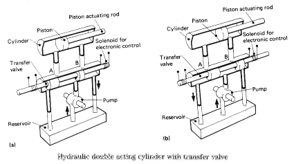
With the spool valve in the position shown in the diagram, the piston would be unable to
move, since no fluid can enter or leave the cylinder. If the valve is moved to the left as
shown in diagram a) both ports A and B become fully open. High pressure fluid from the
pump would then enter the cylinder through A, forcing the piston outwards. Fluid behind the
piston would be expelled through B and returned to the reservoir. Similarly if the valve were
moved to the right as in b), fluid would enter through B and leave through A and the piston
would move inwards. By moving the valve so that ports A and B are only partly open, it is
possible to produce very fine movements in the position of the piston. The valve movements
are usually controlled by a low current solenoid operated via a computer.

Pneumatic Actuators
When considering pneumatic drives it is necessary to take into account the fact that some of
the mechanical work put in is used to compress the air. The system for pumping air into a
pneumatic cylinder is much simpler than the hydraulic system. This is mainly because there
is no point recirculating the air . Used air expelled from the cylinder is released to the
atmosphere via a valve.
A pneumatic system with transfer valve.

Advantages of pneumatic systems
- Pneumatic systems are generally less expensive than hydraulic systems.
- Small leakage's can be tolerated.
- The compressibility of air can be a safety feature e.g. bus and train doors are pneumatic
and will not crush you if you get trapped. This can be of use in the gripper of the robot to
help protect both the robot and the equipment etc. with which it is working.
- Pneumatic drives are faster to respond than hydraulic drives.


