 The exception to this rule is the requirements of the national house building council (NHBC) whose regulations require a clear 50mm cavity.
INFORMATION SHEET
PROJECT TITLE Project No; 17
Cavity wall Incorporating Window Sill, Jambs and Head; CORE
Cavity Wall to be Insulated (Full or partial Fill) 1 of 5
Thermal Insulation.
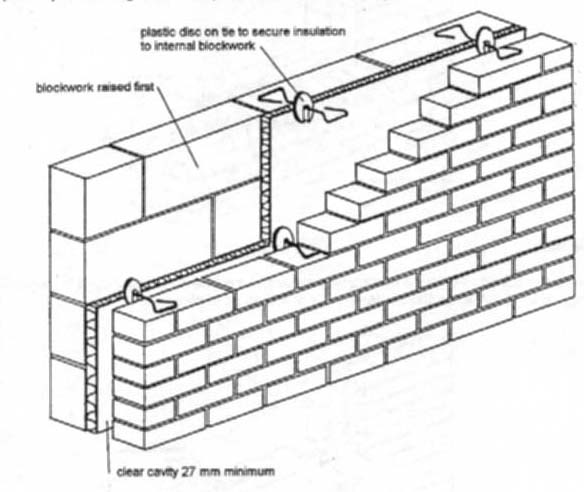
Partial Fill.
Partial fill, as the name implies, only part fills the cavity. As with full fill a high standard of workmanship has to be maintained.
The thickness of insulation used will depend upon the design requirements of the building.
In most situations a 25mm cavity is acceptable.
The exception to this rule is the requirements of the national house building council (NHBC) whose regulations require a clear 50mm cavity.
Brick and Tile Sills.
Brick Sills
The object of a window sill is to remove water that has run off the window. It does it in such a way that it prevents water from reaching the brickwork below the opening, where it would cause dampness and possible staining.
Purpose made sill bricks are manufactured but the common practice is to use a standard brick of engineering quality.
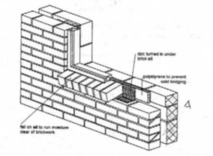 DIAGRAM A
Tile Sills
These are constructed from roofing tiles or purpose made creasing tiles. It is general practice for theses to be fixed after the window is fixed in place.
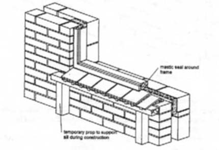 DIAGRAM B
Bridging Openings in Cavity Walls.
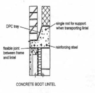
Methods of Bridging Openings
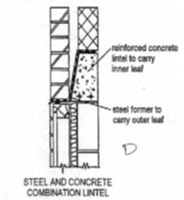
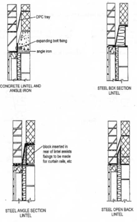
Reinforced concrete lintels, steel lintels or a combination of both can span openings in Cavity walls.
The design of the Lintel will determine the method of construction required at lintel level. This information has to be considered when establishing the brickwork gauge and when bedding the frame to the correct height.
This sectional details shown below represent a range of the lintels that are available.
DIAGRAM C.D.
Bridging Openings in Cavity Walls.
General Information.
DIAGRAM E.F.G.H.
Cavity Trays.
Moisture in Cavities
Moisture in cavities comes from two sources:
Where yhe lintel bridges the cavity it creates a flat surface where moisture can collect and eventually penetrate through to the inside of the building.
To prevent this a damp proof membrane is fitted to the top surface of the lintel.
DIAGRAM I
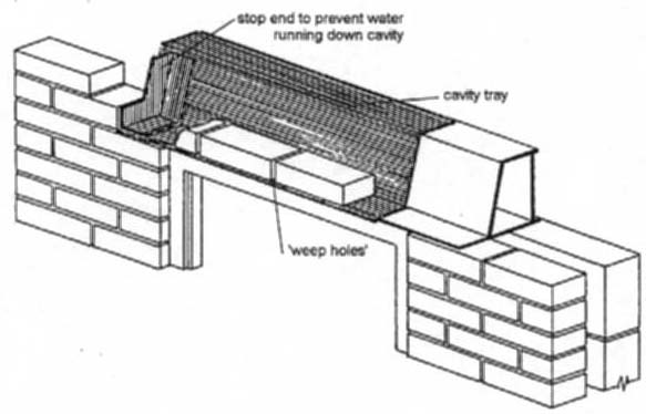
Stop ends should be fitted to the end of DPC trays to prevent moisture running down the cavity.
Cross joints should be left out at intervals along the length of the lintel to allow water to escape. These are known as ‘weep holes’. They can be fitted with fibre filters that conceal the open joint and prevent staining from the lime present in the water.
Some types of steel lintel do not require trays providing they have adequate corrosion protection. They still require stop ends.